Dovetail-Pro
Presentation
The dovetail and finger joints modeling add-in allows you to create precise and efficient assemblies between two solid objects, supporting both metric and imperial systems.
The software automatically calculates the dimensions of the tails based on the desired number and spacing, saving you time-consuming calculations.
The customization tab provides a range of assembly configuration options, allowing you to meet all your modeling needs.
Additionally, the extension offers the capability to model assemblies with rounded edges for router milling, enhancing its versatility.
Finally, you can add a value for a clearance between the tails and the pins, which is useful for creating assemblies with a sliding fit.
The modeling process is streamlined and faster, allowing you to spend more time on other important tasks.
With the dovetail modeling extension, you can improve the accuracy and efficiency of your CAD work.
Currently supported languages : English, French.
(Contact me if you want to add support for another language).
Screenshots
Instructions for use
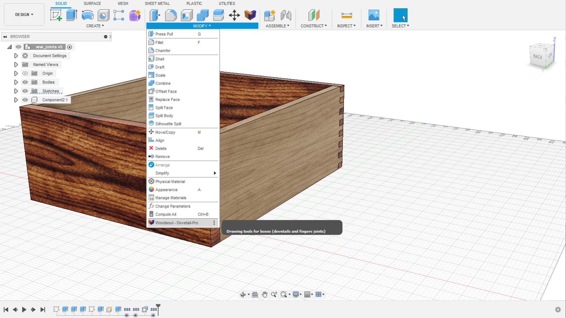
To open the extension, go to the "SOLID" section. You can either click on the Dovetail-Pro icon in the toolbar  , or click on the link in the "Modify" menu.
The selected solids must either completely overlap or not overlap at all. A partial overlap will create an inconsistent result.
Here is an example of solid selections that will or will not work:
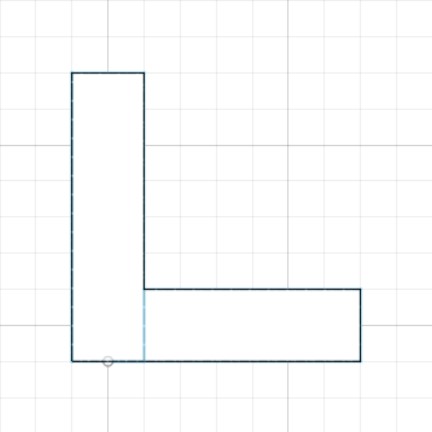 No overlap: OK
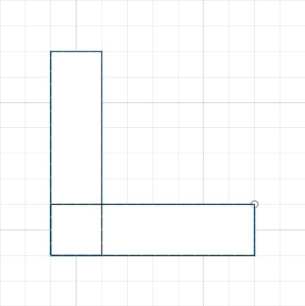 Complete overlap: OK
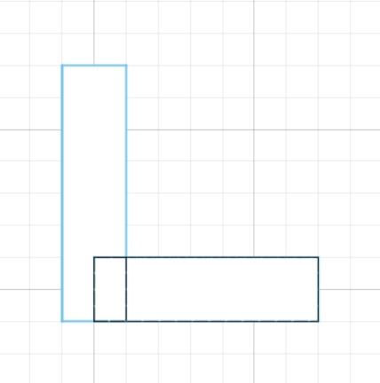 Partial overlap: NOK
The preview of the assembly result takes some time to display. By default, it is disabled, but just check the "Preview result" box to enable it.
When selecting the second solid, the assembly height is automatically calculated. However, you can modify this height, which may be useful for half-blind dovetails.
If an entered value is invalid, the extension will display an message to inform you of the problem.
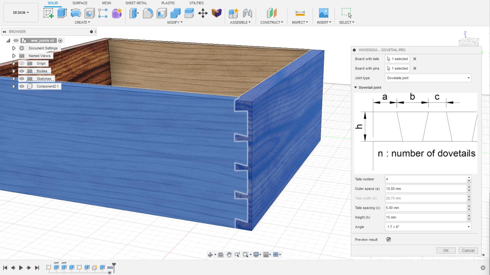
Dovetail joint assembly
In this mode, you can create a dovetail joint assembly by specifying all measurements except the tail width, which will be automatically calculated based on the length of the assembly and the parameters you have entered in the command window.
You can enter:
- Tails number: Number of tails
- Outer space: Shoulder width of two sides of the assembly
- Tails space: Space between the tails
- Height: Height of the assembly
- Angle: Angle of the tails (the proposed angles are the most common in this type of assembly, but a custom angle can be entered)
- Use router bit: If you check this box, you can enter the diameter of the router bit you want to use.
- Clearance: This is the clearance of the tails. It is the space between the tails and the pins for facilitating assembly.
Finger joint
In this mode, you can create a finger joint by specifying a number of tails and a tail height (calculated when selecting the solids).
The width of the tails will be automatically calculated by the extension.
You can enter:
- Tails number: Number of tails
- Tail height: Height of the tails
- Use router bit: If you check this box, you can enter the diameter of the router bit you want to use.
- Clearance: This is the clearance of the tails. It is the space between the tails and the pins for facilitating assembly.
Custom Joint
This type of joint allows you to meet more specific needs. You can modify any dimension if you wish or let the extension calculate it for you.
Like the other joint modes, you will find the angle parameter for the dovetails and the height parameter which can be modified (calculated when selecting both solids).
You can also check the "Use router bit" box to enter the diameter of the router bit you want to use and enter a clearance value.
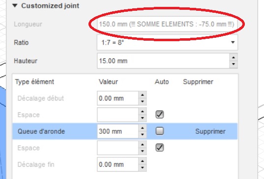
When you activate this type of joint, you will find a table with the elements that make it up.
- Offsets (top and bottom): Offsets allow you to offset the tails on the height of the joint (useful for creating joints at the back of drawers, for example).
- Spacing: These are the spaces between tails. These spaces are added and removed automatically with the tails.
- Tails: You can select the type of tail you want to create via a drop-down menu.
Offsets cannot be removed. You just need to enter their value to zero to make them inactive.
To add a new tail, click on the "Add" button. The program will automatically add the tail with space on either side.
To delete a tail, click on the "Delete" button next to it in the table. This will delete the tail but also any excess spaces.
You can manually enter a width by unchecking "auto" and entering the desired value.
If the sum of the entered values exceeds the length of the joint, a warning will appear in the "Length" field indicating the excess value (see example below).
To install this app/plug-in from Autodesk App Store, run the installer you downloaded.
Uninstallation
If you want to temporarily stop using the add-in, you can unload it by clicking the "Stop" button when the add-in is selected in the list box on the "Add-Ins" tab of the "Scripts and Add-Ins" dialog. To prevent the add-in from being loaded in future sessions of Fusion 360, uncheck the "Run on Startup" option. To fully uninstall the plug-in, first exit the Autodesk product if it's currently running, then run the installer again and select the "Uninstall" button. Alternatively, you can remove the plug-in from your system through 'Control Panel/Programs and Features' (Windows 7/8.1/10/11), just like any other application.
Version history
Support and contact
- Company: Woodsoul
- Developer: Emmanuel OLIVE
If you encounter any issues while using this application or want to suggest modifications, please contact me by email: emmanuel.olive@woodsoul.fr.